
1.5 VDC Pseudocell
Contents
Project Overview
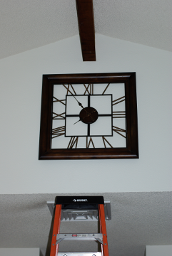
Figure 1. Wall clock above a ten foot ladder.
A large, battery operated, clock is mounted over ten feet high on a wall. The clock runs off of a single 1.5 VDC AA battery. And its electromechanical action drains batteries far too quickly. The goal of this project is to replace the battery with an "always on" power source plugged into an AC outlet.
Whenever its battery runs down, you must fetch a ten foot ladder in order to safely detach the clock from the wall, insert a fresh battery, and reattach it to the wall. It's an easy to postpone chore so the clock spends too much time stopped.
An accessible attic lies directly behind the clock's wall. This project substitutes a pseudo cell, a 1.5 VDC power source, which never drains, for the battery. A pair of wires run behind the clock, through the wall and attic, to a 1.5 VDC power supply mounted on a backboard, located elsewhere.
The most challenging part of this project is the mechanical attachment of the power line to the battery pads. Alligator clips are too flimsy. Pigtails soldered to the battery pads were rejected due to the difficulty of working with the pads.
Using a pseudo cell in the size and shape of a AA battery and relying upon mechanical spring action to hold it in place, seems the easiest option. And, if you use pigtails, you never need to actually remove the pseudocell from its holder.
Circuit Design
The circuit shown in Figure 2 is as lean as possible. Most of the optional components shown in TI's LM317 datasheet [1] are not used because they're superfluous for this application.
A bypass capacitor, C1, is used per TI's recommendation. The load current must be at least 10 mA, worst case, to maintain regulation. A simultaneous linear system is used to compute the optimal values of R1 and R2 necessary to meet the minimal load current requirement.
The datasheet specifies a minimum headroom of 3 VDC. We use Vin = 5 VDC and Vout = 1.5 VDC. There's a 3.5 VDC difference between Vin - Vout, which meets the headroom constraint.
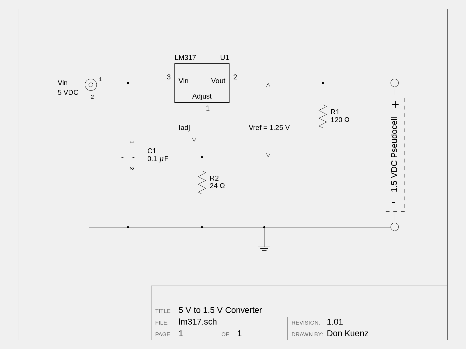
Figure 2. Schematic diagram. (Click on the schematic a couple of times to enlarge.)
Equation 1 comes from TI's LM317 datasheet:
| Vout = Vref (1 + R2 / R1) + (Iadj × R2) | (1) |
The data sheet notes how Iadj is typically ~ 50 𝜇A. So the last term of Equation 1 can be eliminated for most cases. The datasheet specifies Vref = 1.25 VDC.
There's now enough information to setup a simultaneous linear system with a couple of equations. Then use it to calculate the optimal values of R1 and R2.
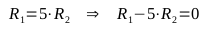
By inspection we see how 5/6 of the output voltage is dropped across R1 and 1/6 of the voltage across R2. In other words, R1 has a 5:1 ratio to R2. This relationship is expressed by Equation 2:
 | (2) |
Next, we take into account the worst case, 10 mA minimal load current. This is expressed as Equation 3:
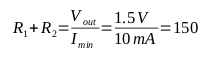 | (3) |
Taken together, these two equations combine to form a simultaneous linear system:
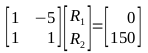 | (4) |
Finally, we use the GNU Octave [2] Scientific Programming Language to solve this system:
octave:1> A = [ 1 -5;
>               1  1 ]
A =

   1  -5
   1   1

octave:2> b = [   0;
>               150 ]
b =

     0
   150

octave:3> r = A\b
r =

   125
    25
The closest standard resistor value combo is 120 Ω and 24 Ω.
Construction
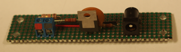
Figure 3. Universal perfboard prototype.

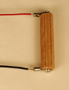
Figure 4. Wooden pseudocell with pigtails.
Figure 3 shows the circuit soldered on a universal perfboard. Acrylic paint denotes the polarity of the 1.5 VDC output connector block.
Figure 4 shows a pseudocell fashioned out of a wooden dowel and pigtails with round crimp connectors on one end, held in place with a couple of small screws. The round connectors are actually soldered to the pigtails and not crimped.
Final Comments
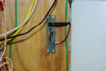
Figure 5. Perfboard mounted on backboard.
Figure 5 shows the perfboard mounted on a backboard. Small screws pass through 1/4" high collars to separate the uneven soldered leads on the perfboard's obverse side from of the backboard.
The black line at top connects to a 5 VDC wallwart. And about one hundred feet of twin pair cable connects the perfboard's bottom terminator to the clock's pseudocell.
Finally, allow me to acknowledge the helpful people at sci.electronic.design and eevblog who provided invaluable insights into this design.
Notes
- [1] LM317 Data Sheet
- [2] GNU Octave
Bill of Materials
| Component | Description | Qty |
|---|---|---|
| R1 | 120 Ω resistor | 1 |
| R2 | 24 Ω resistor | 1 |
| C1 | 0.1 μF ceramic disc capacitor | 1 |
| U1 | LM317 3-Terminal Adjustable Regulator | 1 |
| Pseudocell | see text | 1 |
© 2020 Don Kuenz