
Audio Mixer Amplifier
Contents
Project Overview
An Altoids mixer currently feeds a pair of plastic, PC accessory grade, speakers in my lab. The right speaker contains a builtin analog audio amplifier. As a whole, the sound system's performance is suboptimal due to a few complications:
- The speakers sit on a shelf a couple of feet above ear level.
- The builtin amplifier’s volume must be set to maximum in order to hear the speakers over the ambient noise from a nearby server rack.
- When the speakers are moved closer to the ears, on either side of the operator’s monitor, a horrible ground loop hum becomes noticeable.
- The speakers take up too much table space at that location.
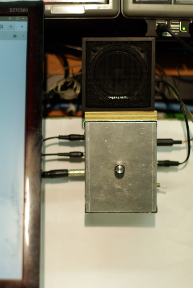
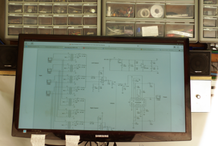
Figure 1 shows a pair of Realistic 40-1250B speakers, at ear level, mounted near the sides of the console monitor. The bookend speakers promise better fidelity at a lower volume. The vintage speakers' compact cabinets are also aesthetically pleasing. Small shelves, on either side of the monitor, attached to the wall behind the monitor, hold the speakers up off of the table top and out of the way. Figure 2 shows a closeup of the right shelf. The bottom of the right shelf also provides a handy anchor point for that portion of the Bud box used as a bracket in this application.
Although an "active" amplifier-based isolator such as the Rohm BA3121F [1] offers a smaller package, my research [2] leads me to believe that larger, bulkier isolation transformers provide the best way to eliminate ground loop hum for this case. The bookend speakers lack a builtin amplifier, which makes it necessary to also add an audio amplifier after the original Altoid's mixer. All things considered, the design goals are:
- Fit everything into a small Bud box mounted under the right speaker shelf.
- Isolate ground loop hum.
- Mix inbound stereo signals.
- Amplify outbound stereo signals.
- Beef up the power supply circuit to handle the increased load.
In the end, the first design goal, to fit everything into a small Bud box, became the hardest to achieve. After a 4" X 2.75" X 1.62" Bud box proved too unreliable it was replaced by a slightly larger 5" X 4" X 3" box. The smaller box used a daughter board to cram components into all available space. It also utilized a troublesome solid wire quick connection system. Front panel ports crowded the volume control knob.
Even though the smaller box was fully operational, it was discarded in favor of a better design. The more spacious, larger box is shown in this article's abstract. Only the volume control appears on its face, which makes it easier to use and cleaner in appearance. Audio line inputs enter on its left side while the power switch, power line, and output are on the right side.
Circuit Design
The stereo audio signal flows from the left to the right side of the schematic shown in Figure 3. (Click on the schematic a couple of times for a larger version.) Each of the four stereo inputs is initially split into a left and right channel. The left channel circuit appears above the right channel on the drawing.
After the split each individual signal component, eight in all, continues on into its own TY141-P isolation transformer [3]. (All transformers' center pins remain unused in this application.) Next, the four left channel transformer outputs are fed into the left mixer while the right channel feeds a separate, identical right mixer.
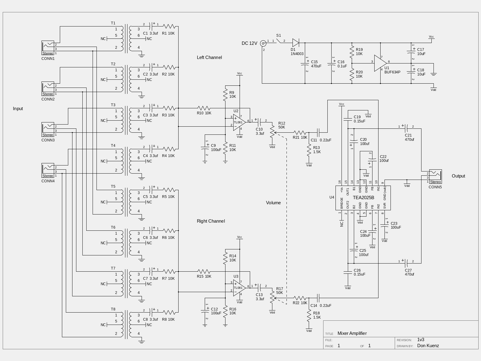
Figure 3. Schematic diagram. (Click on the schematic a couple of times to enlarge.)
Each channel's line level mixer is built around a TL081A JFET-Input Operational Amplifier [4]. The circuit uses each op-amp as a summing inverter with unity gain. The voltages that appear on the four inputs of each channel are added together, inverted, and sent to the mixer output. The voltage divider at each non-inverting input inserts a DC bias to the output that centers the output waveform midway between the voltage rail and virtual ground.
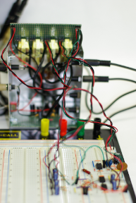
Figure 4. Electronic module
connected to breadboard.
The TL08xA op-amp requires both a positive and negative rail. Research [5] [6] indicates that BUF634 250-mA high speed buffer [7] offers the best solution to divide +12VDC supplied by an external power adapter into ±6VDC for the mixers, for the time being. As shown in Figure 4, the electronic module was then connected to a breadboard to verify this finding in a lab environment. Indeed, a simple resistor and zenier diode splitter introduced noticeable audio distortion into the sound stream.
The upper right corner of the schematic shows the final power circuit. It inputs +12VDC from an external adapter and creates a virtual ground for the mixers. After each channel is mixed, it then passes through a ganged potentiometer to feed a the twin inputs of TEA2025 audio amplifier [8] operated in stereo mode.
The audio amplifier is driven by a +12VDC rail. C10 and C13 isolate the channels to enable a sleight of hand whereby the virtual ground is transposed to the negative rail. That way, the audio amp utilizes all available power.
In addition to the mixers, the virtual ground circuit was originally designed to meet the current demand of an audio amplifier operated at +6VDC. In this latest design iteration, where the amplifier is no longer directly connected to the virtual ground, it may be possible to substitute a TLE2426 for the BUF634 without introducing additional distortion.
Construction
The mixer amplifier utilizes a modular design to help squeeze its components into the smallest possible enclosure. This approach also makes it easier to troubleshoot and experiment with enhancements.
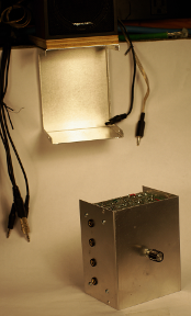
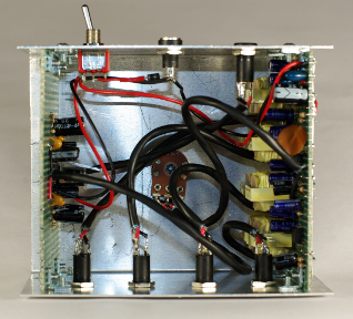
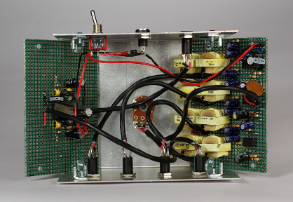
As shown in Figures 5 and 6, half of the mixer-amp’s 5" x 4" x 3" Bud box enclosure holds all of the electronics, except the external power adapter. Each side board is normally secured with four ell brackets, one in each corner. Removing one screw from the two side board corners that are distal from the front panel makes the side board swingable. It's easier to solder and debug components with the added flexibility.
Stereo coax carries all audio signals within the module while stranded hookup wire is used for power connections. From the viewer's perspective the audio amplifier appears on the left side board of Figure 6, while the transformers, power supply, and mixers appear on the right side board.
Final Comments
The project meets or exceeds all major design goals. It outputs exquisite music. The sound is so clear that background music does not detract from ham radio streams. It acts as a pair of virtual headphones that provide headphone quality separation.
A project’s never finished; it is only abandoned. As mentioned above, substituting a TLE2426 for the BUF634 is a future possibility. The elimination of C1-C8 and R1-R8 to feed the isolation transformer output directly into summing junctions offers another intriguing future enhancement. Gathering Total Harmonic Distortion data may also take place at a later date.
Although this project started out with stripboard, it proved too uncompromising in the long run. During the second iteration of motherboard assembly, universal two sided PCB was substituted for the stripboard. The universal board enabled quick assembly, rapid debugging, and easy experimentation. The original daughterboard was then dropped during the third iteration of motherboard assembly when the swinging sideboard concept was adopted.
Notes
- [1] Rohm BA3121F Ground Isolation Amplifier
- [2] An Overview of Audio System Grounding and Interfacing by Bill Whitlock
- [3] TY141-P isolation transformer datasheet
- [4] JFET-Input Operational Amplifier Datasheet
- [5] Virtual Ground Circuits
- [6] The top three ways to split a voltage rail to a bipolar supply
- [7] BUF634 250-mA high speed buffer datasheet
- [8] TEA2025 audio amplifier datasheet
Bill of Materials
| Component | Description | Qty |
|---|---|---|
| R1-R11,R14-R16,R19-R22 | 10K resistor | 18 |
| R12 and R17 | 50K ganged linear taper potentiometer | 1 |
| R13,R18 | 1.5K reisistor | 2 |
| C1-C8,C10,C13 | 3.3uF 50V capacitor | 10 |
| C9,C12,C20,C22-C25 | 100uF 16V capacitor | 7 |
| C15,C21,C27 | 470uF 25V capacitor | 3 |
| C16 | 0.1uF ceramic capacitor | 1 |
| C17-C18 | 10uF 35V tantalum capacitor | 2 |
| C19,C26 | 0.15uF capacitor | 2 |
| CONN1-CONN5 | 70-534B insulated stereo jack | 5 |
| T1-T8 | TY-141P audio isolation transformer | 8 |
| U1 | BUF634P 250-mA high speed buffer | 1 |
| U2,U3 | TL081A JFET input op amp | 1 |
| U4 | TEA2025 audio amplifier | 1 |
© 2019 Don Kuenz