

Altoids audio mixer
Contents
Problem description
My lab contains a single pair of speakers, shoe horned onto the overcrowded space on top of a row of part bins. If you look carefully near the left edge of the photo in Figure 1 you can see the left speaker mostly obscured by books under the big black book. The Altoids jelly bean mixer is shown in operation along the mid-right edge of that photo, next to the right speaker.
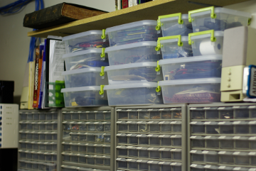
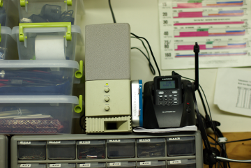
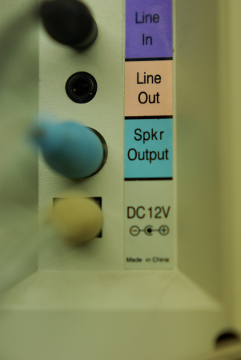
Figure 3. Closeup of right speaker's jacks.
Figure 2 shows a closer view of the mixer wedged in between the right speaker and the Plantronics™ headset. Note the precarious juxtaposition of the speaker and the headset.
The close up of the rear view of the right speaker shown in Figure 3 reveals one Line In jack along with a 12 VDC power jack. A PC, a ham radio, and miscellaneous other audio devices must share that single Line In jack. In the past, to change the audio device connected to the speaker system you had to manually rotate the right speaker and then insert the stereo cable of the new device into the Line In jack. Most of the time this process caused the precariously positioned headset to tumble to the table below.
That's the crux of the problem. A headset that consistently fell down whenever the speaker was rotated. The solution was to build a mixer that allowed three audio cables to simultaneously connect to the Line In jack and obviate the need to rotate the right speaker.
Mixer design
The line level mixer is built around one TL084A JFET-Input Operational Amplifier. Although the schematic below shows two separate TL082A op-amps that's an artifact of the software used to create the schematic. In reality, op-amp 1 and op-amp 4 of a TL084A are used. You may optionally use op-amp 1 and op-amp 2 of a TL082A. (Click on the schematic for a larger version.)
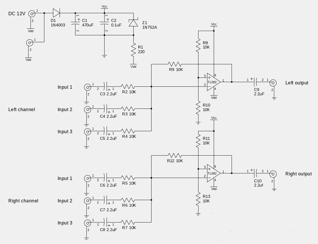
Figure 4. Schematic diagram.
The circuit uses each op-amp as a summing inverter with unity gain. The voltages that appear on the three inputs of each channel are added together, inverted, and sent to the output. The voltage divider at each non-inverting input inserts a DC bias to the output that centers the output waveform midway between the voltage rail and virtual ground.
The TL08xA op-amp requires both a positive and negative rail. So the +12 VDC power source is nominally split in half by Z1 and R1. A DC bus is implemented to enable a single wall wart to power both the speaker system and the mixer.
Altoids packaging
When empty, the iconic Altoids tin makes a great box for small devices. It's free (after its contents are eaten) and it acts as an EMR shield. Figure 5 shows what's under the cover. It's hard to see, but a piece of cardboard insulates the bottom of the strip board from the tin.
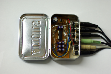
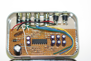
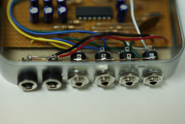
Figure 7. Audio and power jacks.
Figure 6 shows a closeup of the strip board. The red and black wires connect the strip board to the 12 VDC bus. The yellow, blue, and green wires connect the stereo audio jacks to the inputs of each stereo channel. One channel is on the upper half and the other channel is on the lower half of the strip board. The white wires connect the output to a stereo jack on the left.
The power circuit is at the left of the strip board. It contains a filter and the circuit that creates a virtual ground.
Drilling the holes for the jacks shown in the Figure 7 was the most difficult task in the project. The metal is thin and the tin is hard to position in a drill press. You must also use insulated power jacks. Although the wall wart outputs 12 VDC over ground, the circuit sees it as a nominal ±6 VDC.
© 2019 Don Kuenz