
Power Bank Keepalive
Contents
Project Overview

Figure 1. MP3 player.
The MP3 player shown Figure 1 is available from online retailers. It's a handy little device when you want to listen to music and audio books as you trek about on your feet or spin up a mountain on your bicycle. Screenless MP3 players with a minimal number of buttons prove to be the most reliable for my needs. A too tiny battery is their only downfall.
Although a brand new battery lasts about an hour, the play time quickly falls to fifteen minutes or less after a few uses. And even one hour isn't long enough me.
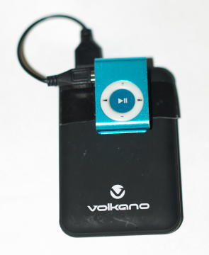
Figure 2. Power bank mod.
The first fix, shown in Figure 2, seemed simple enough - buy a power bank then duct tape the MP3 player to it. And use a short Type-A to Mini Type-B USB cable to connect the two. Easy peasy and good to go.
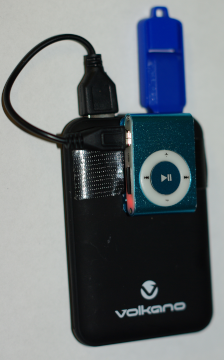
Figure 3. USB memory mod.
Only it doesn't quite work out the way you imagine. Because the big battery shuts down after about 15 seconds. One star complaints online talk about poor quality USB power banks. It indicates a widespread, poorly understood problem caused by lack of documentation.
After research reveals an automatic shutdown utilized in power banks a second fix comes to mind: stick something else into the power bank to adequately load it enough to prevent shutdown. A mouse fob won't work. But flash memory does. Figure 3 shows the state of the art thus far.
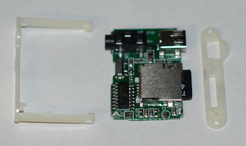
Figure 4. Internal battery removed.
The contraption in Figure 3 comes with its own set of problems. It's not rugged - you know it's only a matter of time before flex stress breaks the big blue flash drive into pieces in your pocket. And the short, stiff USB cable sticks out like a sore thumb.
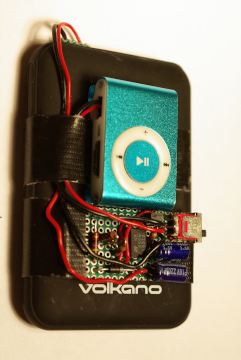
Figure 5. Final product.
Worse yet, a battle of the batteries eventually ensues. Mostly because when the MP3 senses an external source, it wants to go into small battery charge mode. You have to tease it back into play mode. Audio distortion and downright failure can occur as the batteries fight it out for dominance.
The third fix is to remove the small battery altogether, as shown in Figure 4. The fourth and final fix is to replace both the USB cable and the thumb drive with the more ruggedly compact circuit in Figure 5.
Circuit Design
The keepalive circuit [1] uses a 555 [2] as an astable multivibrator. Followed by a transistor switch with a free-wheeling diode, robust enough to handle the periodic 100 mA drop.
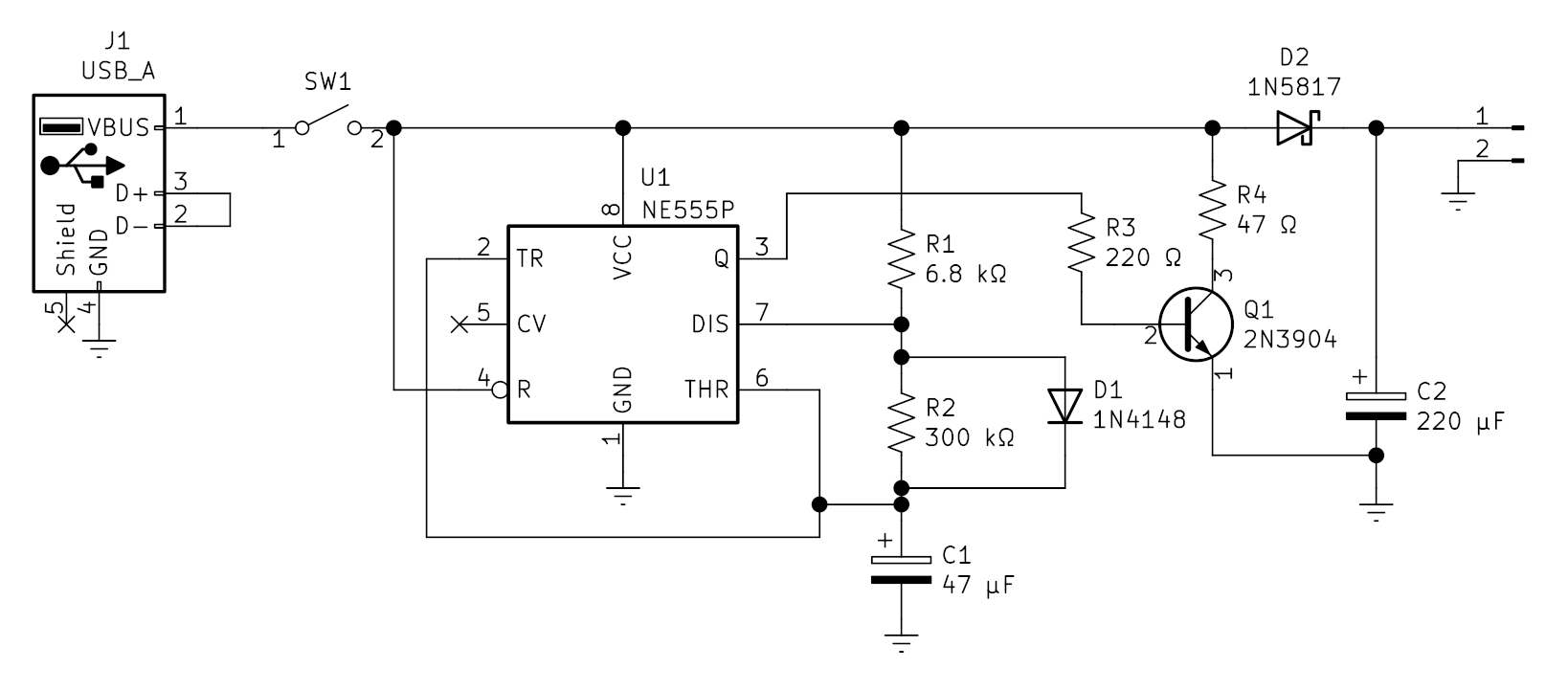
Figure 6. Schematic diagram. (Click on the schematic a couple of times to enlarge.)
For the 555 topology shown above, the governing equations become:
| ton = 0.693 * R1 * C1 | (1) |
| toff = 0.693 * R2 * C1 | (2) |
The component values used in the circuit give ton = 223 ms, and toff = 9.8 s.
Construction
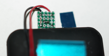
Figure 7. DIY Type-A USB connector.
The DIY Type-A USB connector in Figure 7 is fashioned from tiny piece of universal prototype board with a smaller thin cardboard backer used to insulate the board's backside from the bank's female USB shield. The backside of the board is filed down first, to make it as smooth as possible, in order to prevent any solder spike or wire pokes through the cardboard.
If you examine Figure 7 carefully you can see how the Type-A connector follows physical power protocol. Pins 1 and 4 connect first. Followed by a D+ to D- horizontal connection. The bare #24 wires on the surface of the prototype board add enough depth to press firmly against the power bank's built-in female pads.
Final Comments
Figure 8 shows Logic Analyzer output captured from a circuit in operation. A period T ~ 11.25 seconds and the pulse width ~ 300 mS are obtained from the image by inspection. Within tolerances, the measured times agree nicely with theoretical times.
As is, after a couple of weeks of daily 2 - 3 hour trials, the battery has yet to register any sign whatsoever of drain. The drudgery of daily MP3 re-charges is now vanquished from my life.
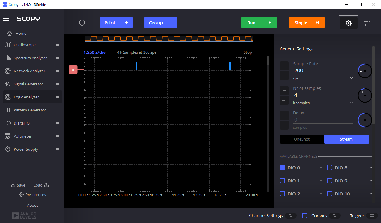
Figure 8. Pull-down pulse timing. (Click on the image a couple of times to enlarge.)
The keepalive's efficiency can be compared to an always-on alternate circuit (eg a 50 Ω resistor). In this case, we can use this formula to calculate the keepalive's efficiency:
 | (3) |
Field trials indicate the DIY Type-A USB connector as a weakness, prone to breakdown. And more robust alternatives are sought.
Notes
Bill of Materials
| Component | Description | Qty |
|---|---|---|
| R1 | 6.8 kΩ resistor | 1 |
| R2 | 150 kΩ resistor | 1 |
| R3 | 220 Ω resistor | 1 |
| R4 | 47 Ω resistor | 1 |
| C1 | 47 μF capacitor | 1 |
| C2 | 220 μF capacitor | 1 |
| D1 | 1N4148 diode | 1 |
| D2 | 1N5817 Schottky diode | 1 |
| Q1 | 2N3904 NPN transistor | 1 |
| U1 | NE555 timer | 1 |
| S1 | slide switch | 1 |
© 2022 Don Kuenz